Panorama Photography: Plan Every Frame and Preview the Whole Scene
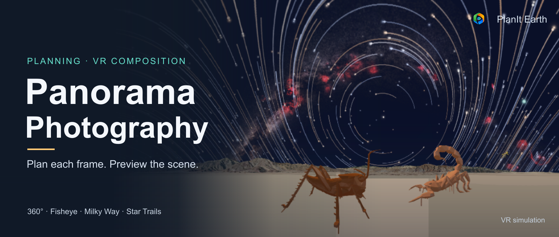
Plan single-row, multi-row, 360° and fisheye panoramas in PlanIt Earth. Preview twelve projections, check each frame, and compose Milky Way arches and star trails in VR.
A note before we begin
With this update, the panorama feature has finally come together as a much more complete tool.
When PlanIt Earth first launched, panoramas had only a calculator card, and both the calculations and the workflow still needed work. Now the shooting plan, VR composition preview, projection comparisons, and the coverage of each photograph are connected in one workflow.
I would especially like to thank Eason. He contributed many suggestions that helped improve the panorama card and simulation. He also took the shooting plans calculated by PlanIt into the field, photographed the sequences, and stitched them in PTGui to check whether they produced complete images. That practical testing helped me find and resolve many details.
This update is also a chance to explain an important goal I have for PlanIt Earth.
I have always developed PlanIt Pro on my own, with limited time and energy. Development often follows the so-called “80/20 rule”: roughly 20% of the time may get a feature to 80%, while the remaining 20% of the details may take another 80% of the time. I simply did not have enough time, so some features had to be put aside at 80%, or at most 85%. Some users have told me that certain features in Pro feel as though they are missing that last little bit. This is often the reason.
With PlanIt Earth, I want to take each feature further. I would not claim that panoramas are now 100% complete, but measured against what I set out to build, I would put them at least 95% complete. From calculation and simulation to practical testing, the main steps and their details are now in place.
I will keep working this way. Whenever I finish improving a feature, I will write an article like this one: both a summary of its development and a complete guide to using it, so you can learn the process and put it into practice.
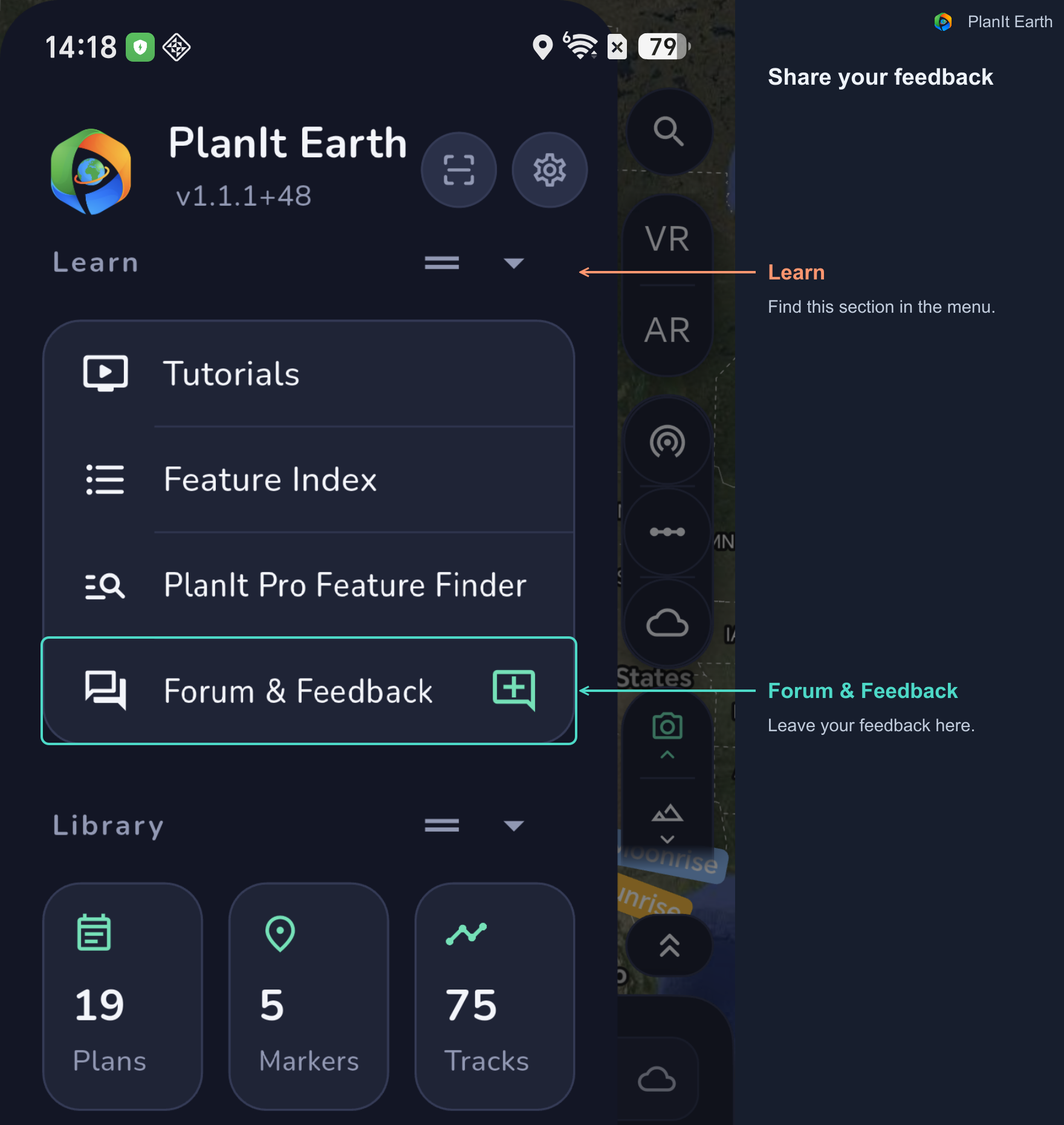
If you want to make sure I see your feedback, the best way is to open Forum & Feedback in the menu and leave me a message there.
A single photograph may not be wide enough for a mountain range, a city skyline, or a Milky Way arch above the landscape. A panorama combines photographs taken in different directions into one larger image.
The composition begins before the first exposure. Focal length, camera orientation, overlap, rotation steps, row elevations, and the final projection all affect the result. PlanIt Earth connects these decisions: use the Panorama card to calculate a shooting plan, then open the VR viewfinder to preview the scene and check the area covered by each photograph.
This guide covers single-row and multi-row panoramas, full 360° spheres, fisheye lenses, Milky Way arches, and star trails. There are many screenshots, so reading on a computer while following the steps on your phone will be easier. Click any figure to enlarge it.
1. Decide how much of the scene to include
Single-row panorama. Keep the camera at the same elevation and rotate horizontally between exposures. This works well for mountain ranges, coastlines, and skylines. The lens and camera orientation determine how much sky and foreground one row includes.
Multi-row panorama. Photograph one row, change the camera's elevation, and photograph the next. Use this when you need more vertical coverage or want to build a detailed image with a longer lens.
360° horizontal panorama. Photograph a complete circle so the first and last frames can overlap. A full horizontal turn does not automatically include the zenith and nadir.
Full 360° sphere. Cover every direction: 360° horizontally and 180° vertically, from straight up to straight down. You can display the result as a spherical panorama or explore compositions such as a little planet. Check the plan for any separate zenith and nadir shots.
Start with the composition you want. A mountain range may need mostly horizontal coverage; a Milky Way arch needs enough vertical coverage too. A full sphere gives you more freedom to choose the viewing direction later.
2. Open the Panorama card and start with Simple mode
Open the upper-left menu, find Cards, and choose Photo. On the Photo Tools page, tap Panorama.
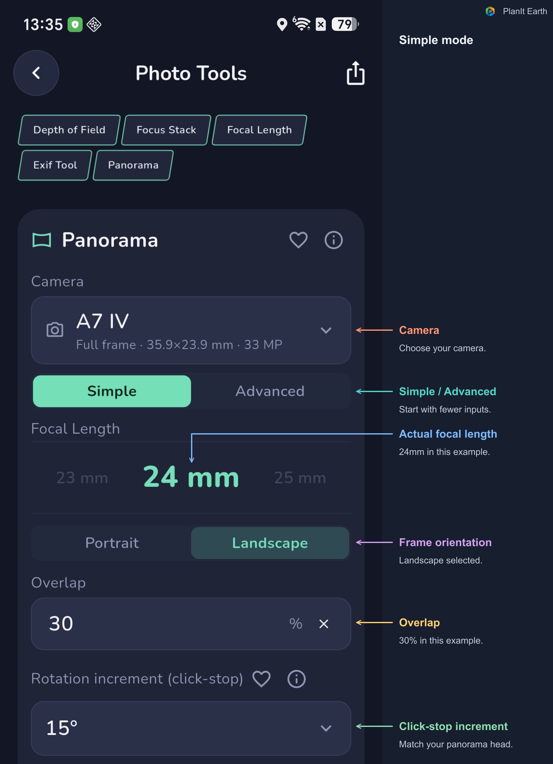
Select your actual camera so the calculation uses the correct sensor dimensions. Enter the lens's actual focal length. The same focal length covers different angles on different sensor sizes. The 35mm-equivalent value helps compare fields of view; the focal-length input still uses the actual lens setting.
In Simple mode, choose the camera orientation, overlap, rotation increment, and total coverage. The card calculates the number of rows and columns and the rotation between photographs.
Portrait and Landscape describe each source photograph
Neither orientation is always better. For a single-row landscape panorama, Portrait is often a useful starting point: each frame includes more sky and foreground, which can keep a scene within one row. Each frame is narrower horizontally, though, so the same horizontal coverage usually takes more photographs.
Landscape covers more width per photograph, but includes less height. It can be convenient for a shallow horizontal scene; if you need more sky and foreground, you may have to add rows.
For a multi-row panorama, compare both orientations using the same camera, focal length, overlap, and total coverage. Check the number of rows, total frames, and how easily you can follow the shooting sequence. The smaller frame count is useful only if the plan still includes the composition you want.
Portrait and Landscape describe each source photograph. The final panorama's aspect ratio also depends on the total coverage and projection, so Portrait source photographs can still produce a wide landscape panorama.
Overlap gives adjacent photographs something in common
Stitching software matches details shared by neighboring photographs. Overlap controls how much of that common area is planned. The current card offers values from 15% to 65%.
More overlap generally means more photographs for the same coverage. Choose it with your lens, subject detail, and stitching workflow in mind. Featureless sky, fog, and water can be difficult to match; check whether adjacent frames will include stars, landscape details, or other useful features.
Plan by angles or by rows and columns
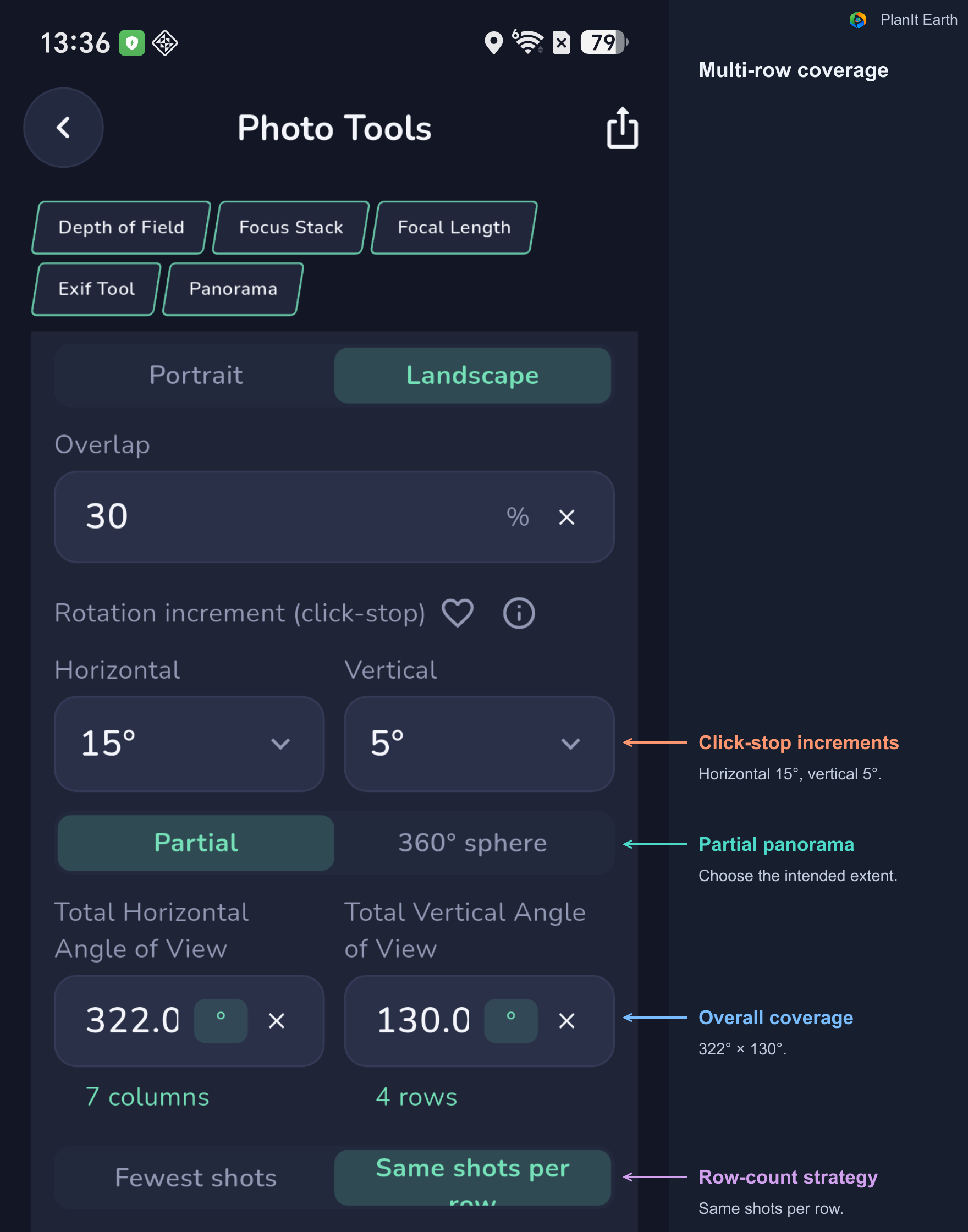
Enter the Total Horizontal Angle of View and Total Vertical Angle of View when you know the coverage you want. Tap the ° button inside a coverage field to switch from degrees to a number of columns or rows. Tap the unit again to switch back to degrees.
For a single row, the vertical coverage setting can be 0. This selects a single-row plan; the lens still has its normal vertical field of view.
3. Turn the calculation into movements you can repeat
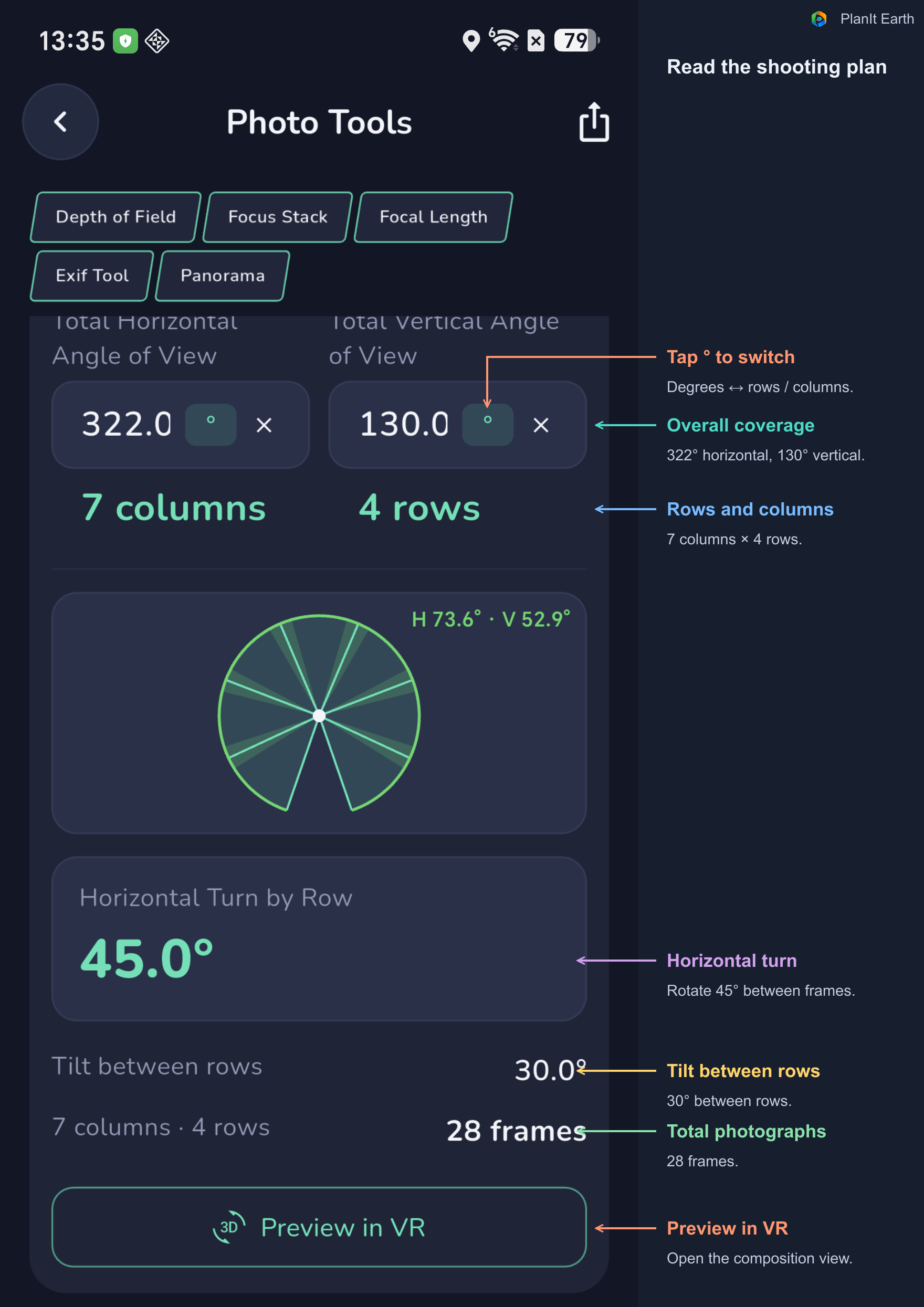
Read three results before shooting. Horizontal Turn by Row tells you how far to rotate after a photograph. Tilt between rows tells you how to move to the next row. The column, row, and total-frame counts let you check the size of the job.
This example uses an A7 IV at 24mm in Landscape orientation, with 30% overlap and approximately 322° × 130° coverage. In Simple mode, the result is 7 columns and 4 rows: 28 frames, with 45° horizontal steps and 30° tilt between rows. Recalculate when you change the camera, lens, or coverage.
Enter the click-stop increment of your head
Some panoramic heads rotate through fixed detents. If each click is 15°, choose 15° for the rotation increment. The calculation uses suitable multiples of the increment so you can reproduce the movement by counting clicks.
For example, a 45° turn is three 15° clicks. Use the angle shown in your own plan. Rounding to a usable detent may reduce the step and increase overlap. Choose None when the head rotates freely or accepts an arbitrary angle.
Simple mode uses one click-stop setting. Advanced mode lets you specify horizontal and vertical increments separately.
Recognize the controls on the hardware
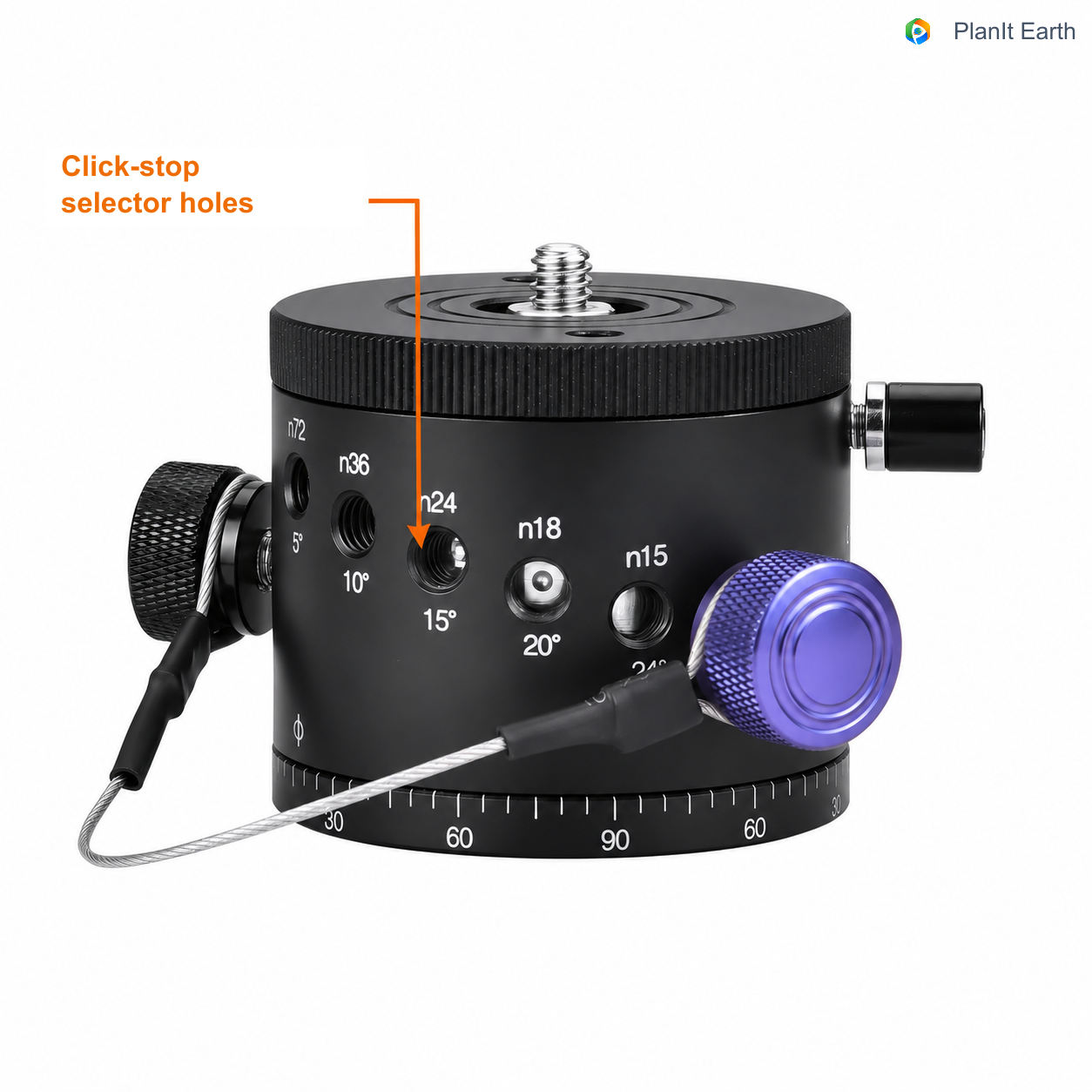
On this type of rotator, different holes select different intervals. n24 / 15° means 24 positions in a complete turn, with 15° between positions; n36 / 10° means 36 positions at 10° each. Enter the angle for the position you select.
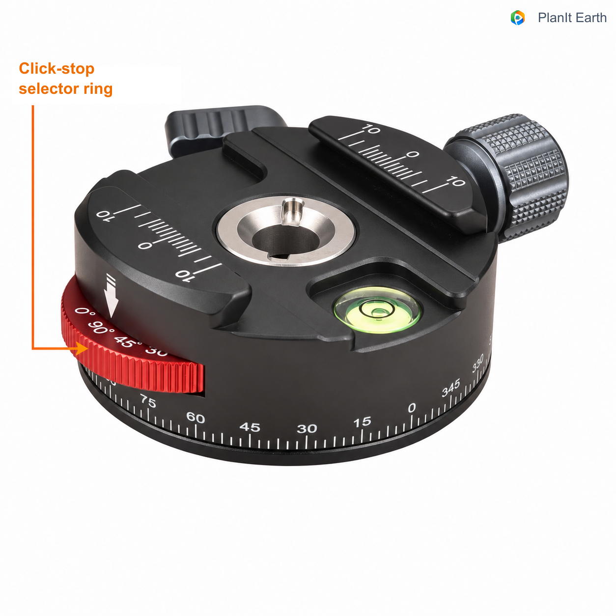
Another design marks the intervals around a selection ring. This example shows markings including 90° and 45°, together with a separate rotation scale. Follow the head's instructions to select the detent interval, then enter that interval in the card.
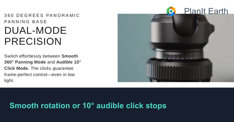
Some ball heads also offer indexed rotation. For example, the HEIPI KF50 provides smooth rotation and an audible 10° click mode. Enter 10° for the horizontal rotation increment when using that mode. Product illustration and description: HEIPI's official product page.
A 10° click stop does not limit you to turning only 10° at a time. If the plan calls for 30°, move three clicks; for 60°, move six. It is a straightforward way to repeat the movement. The key is the head’s smallest click-stop interval: larger turns can be made by counting multiple clicks, but a turn that is not an exact multiple of that interval cannot be reached precisely by counting clicks alone. Enter the smallest interval in the card, then count the clicks needed for the calculated turn.
4. Use Advanced mode for more control over multiple rows
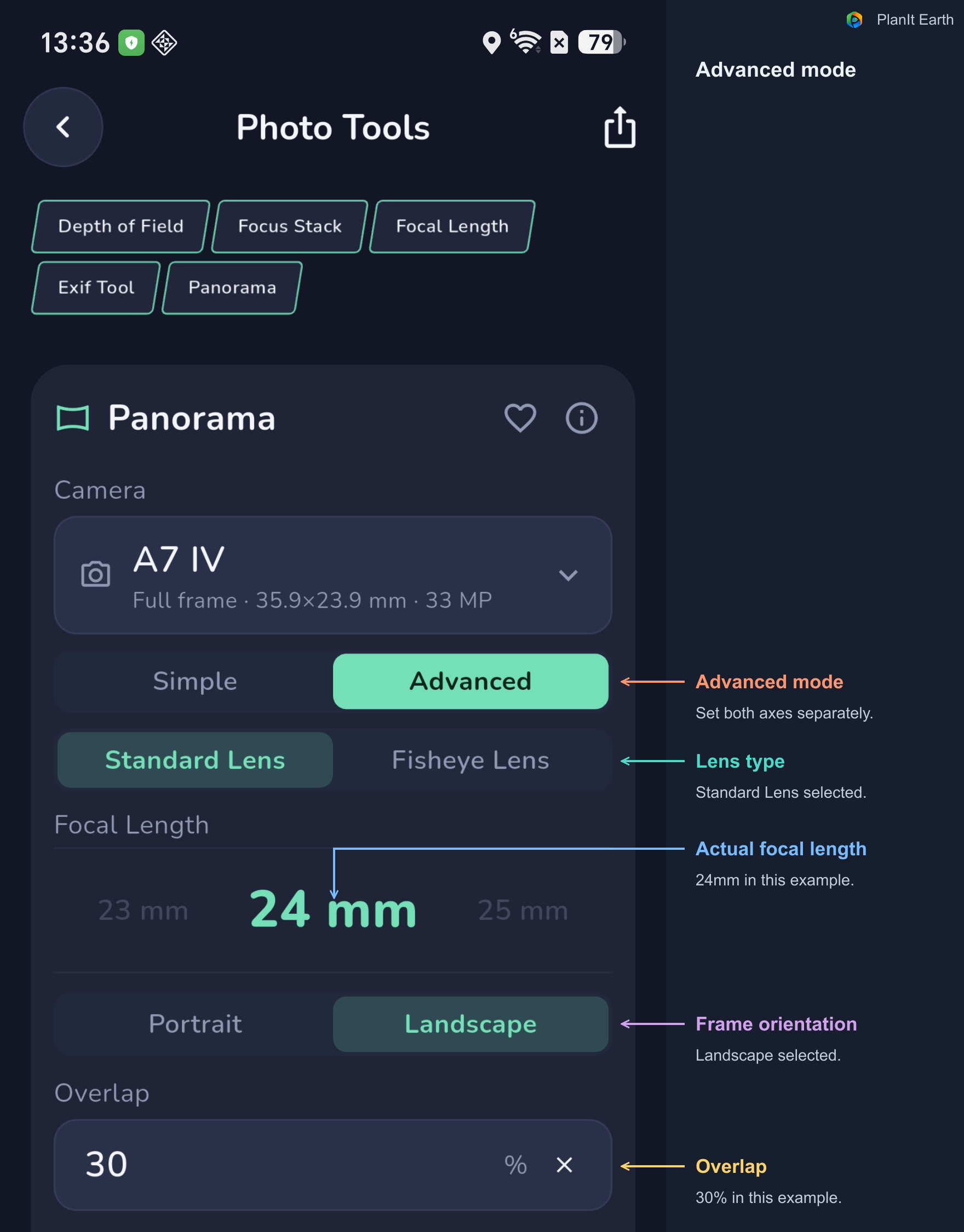
In Advanced mode, choose Standard Lens or Fisheye Lens, set the two rotation increments independently, and select a partial panorama or a full 360° sphere.
The illustrated click-stop settings are 15° horizontally and 5° vertically. Enter the actual interval for each axis. If the vertical axis moves freely, choose None for that axis.
Fewest shots or Same shots per row
As the camera points closer to the zenith or nadir, the horizontal range covered by a frame changes. Advanced mode calculates coverage row by row.
Choose Fewest shots to use the required number for each row. Choose Same shots per row for a repeated pattern that may be easier to follow in the field. The latter can require more photographs.
Read the elevation, shot count, and turn angle for every row. For multi-row night-sky work, knowing the sequence in advance makes the shooting process easier.
Horizon Row Elevation sets the starting arrangement for a sphere
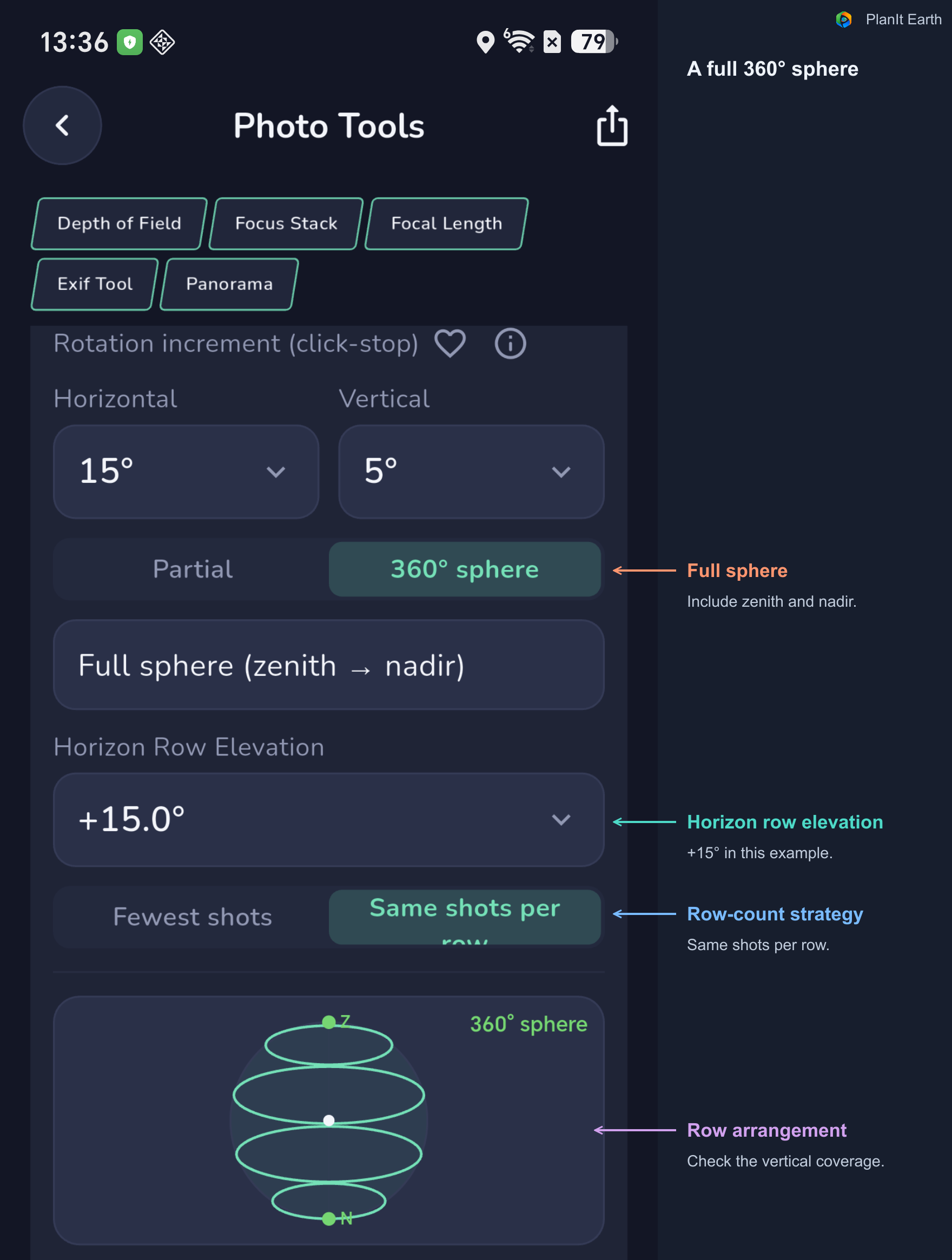
After selecting 360° sphere, choose a Horizon Row Elevation, or use its automatic value. This controls the arrangement of the rows. The result lists their elevations and any required zenith and nadir shots.
When photographing the nadir, plan how you will handle the camera support appearing in the image. Decide what ground detail you want to keep, then capture the additional material your stitching workflow requires.
5. Include a fisheye lens in the shooting plan
A fisheye lens covers a very large angle in one frame. It is often useful for photographing the whole sky or a full sphere with relatively few photographs. Select Fisheye Lens in Advanced mode, then choose the appropriate focal length and Image Circle.
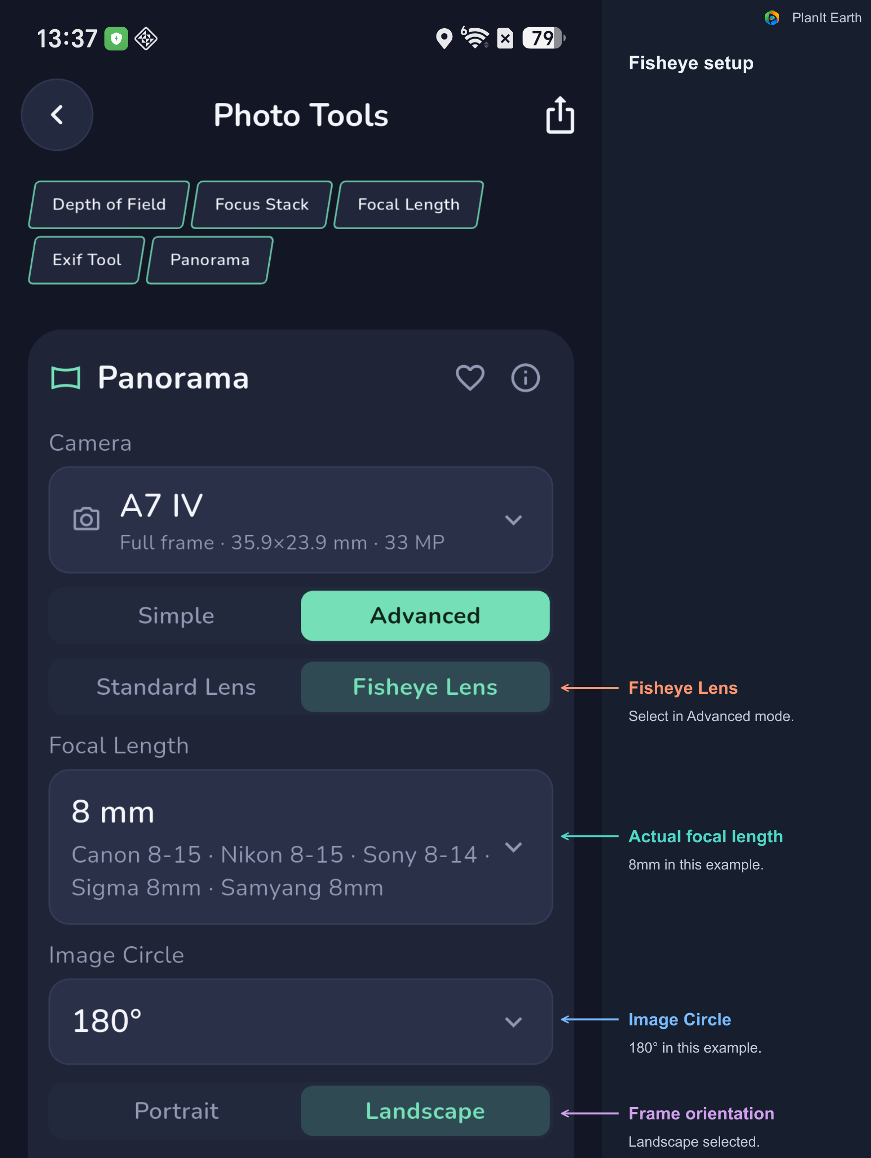
Image Circle is expressed as an angle here. Actual coverage also depends on how the sensor crops the circular image, so check the camera, focal length, image-circle angle, and orientation together.
The current calculation uses an equisolid-angle fisheye model. Individual lenses can have different projections and edge behavior. Test your own lens and check overlap near the edges before an important shoot.
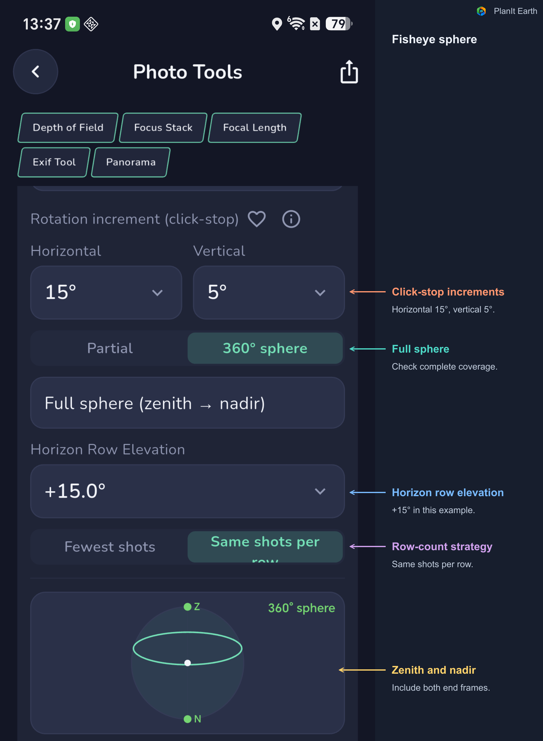
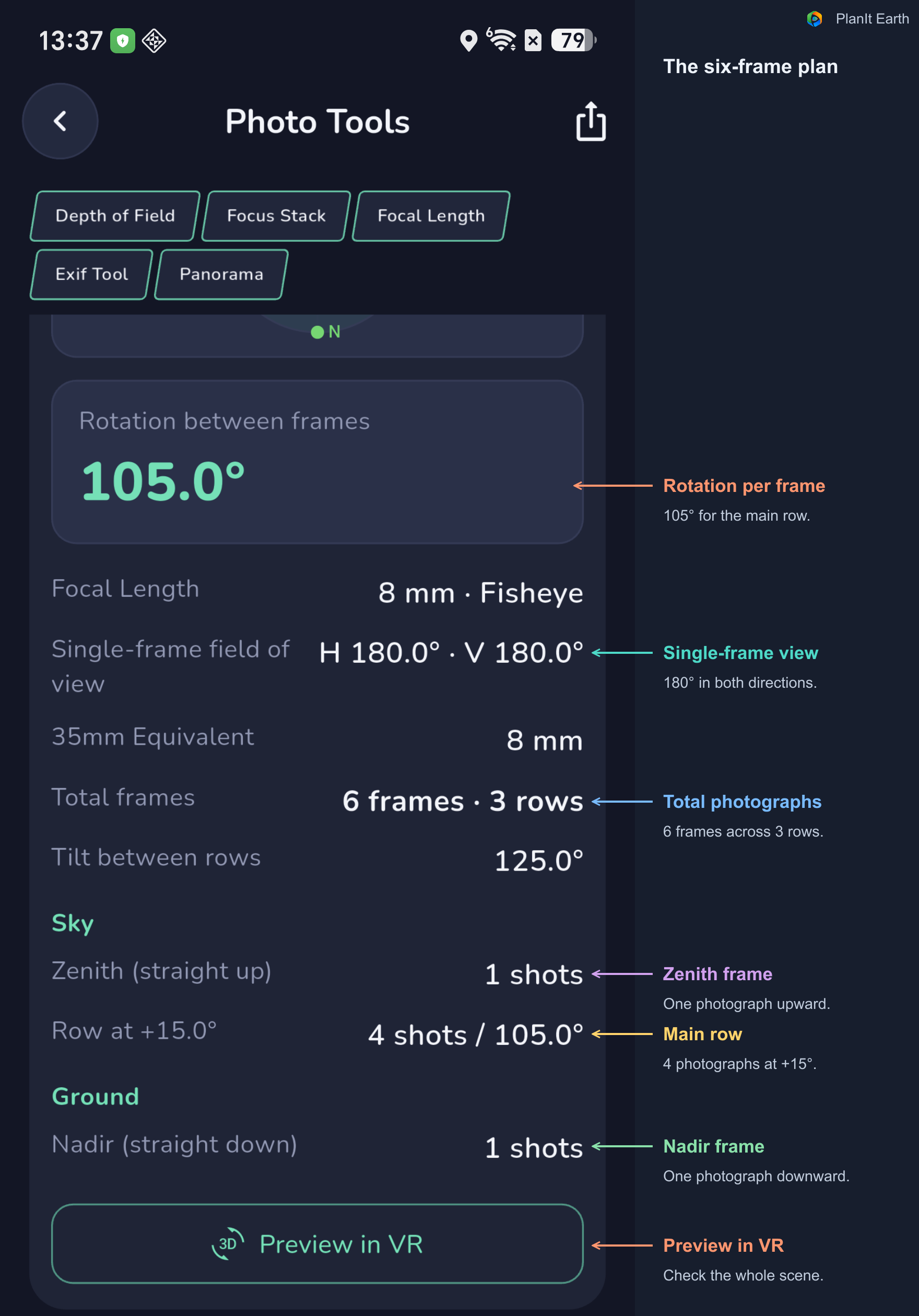
The illustrated 8mm, 180° example produces a six-frame plan with the shown sensor, overlap, detents, and row elevation: one zenith frame, four frames in the main row, and one nadir frame. Use the result for your own settings rather than assuming every fisheye needs the same number.
6. Open VR and compose the whole panorama
Tap Preview in VR at the bottom of the Panorama card. You can also open the VR viewfinder and select Panorama Simulation from its controls. The card and VR simulation share their panorama shooting settings.
First set the camera position, date, and time on the map. In VR, use the terrain background to compare the mountains, horizon, and sky. Open Panorama Simulation and tap Render when the scene needs to be generated or updated. Wait for loading to finish before assessing the composition.
Check the whole scene first, then adjust the coverage and direction, and finally examine the area covered by each photograph.
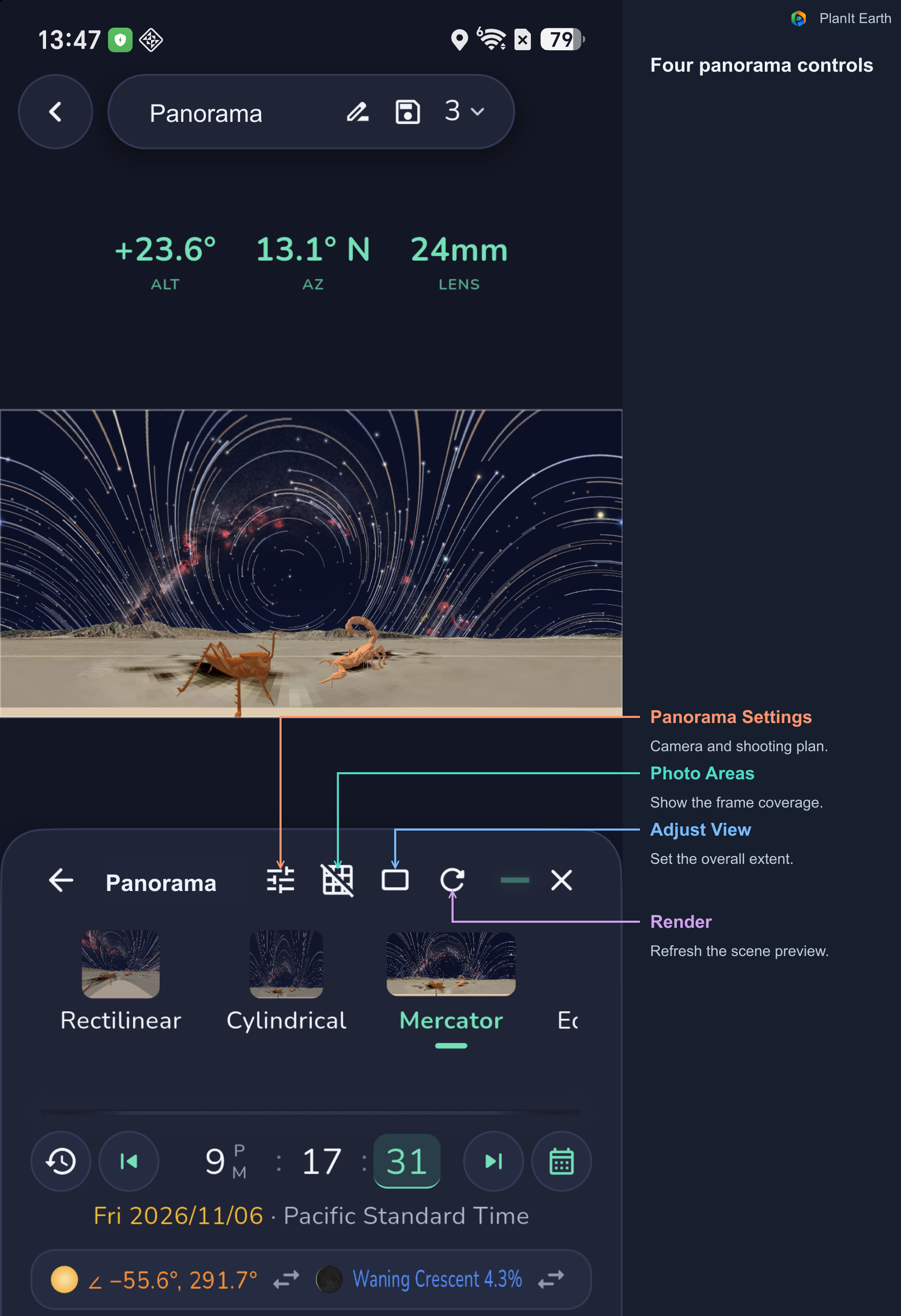
This example includes two sculptures: a grasshopper and a scorpion. Lowering the horizon leaves more room for the star trails. Establish the balance between sky and foreground before checking the individual controls.
Panorama Settings: check the lens, coverage, and shooting plan
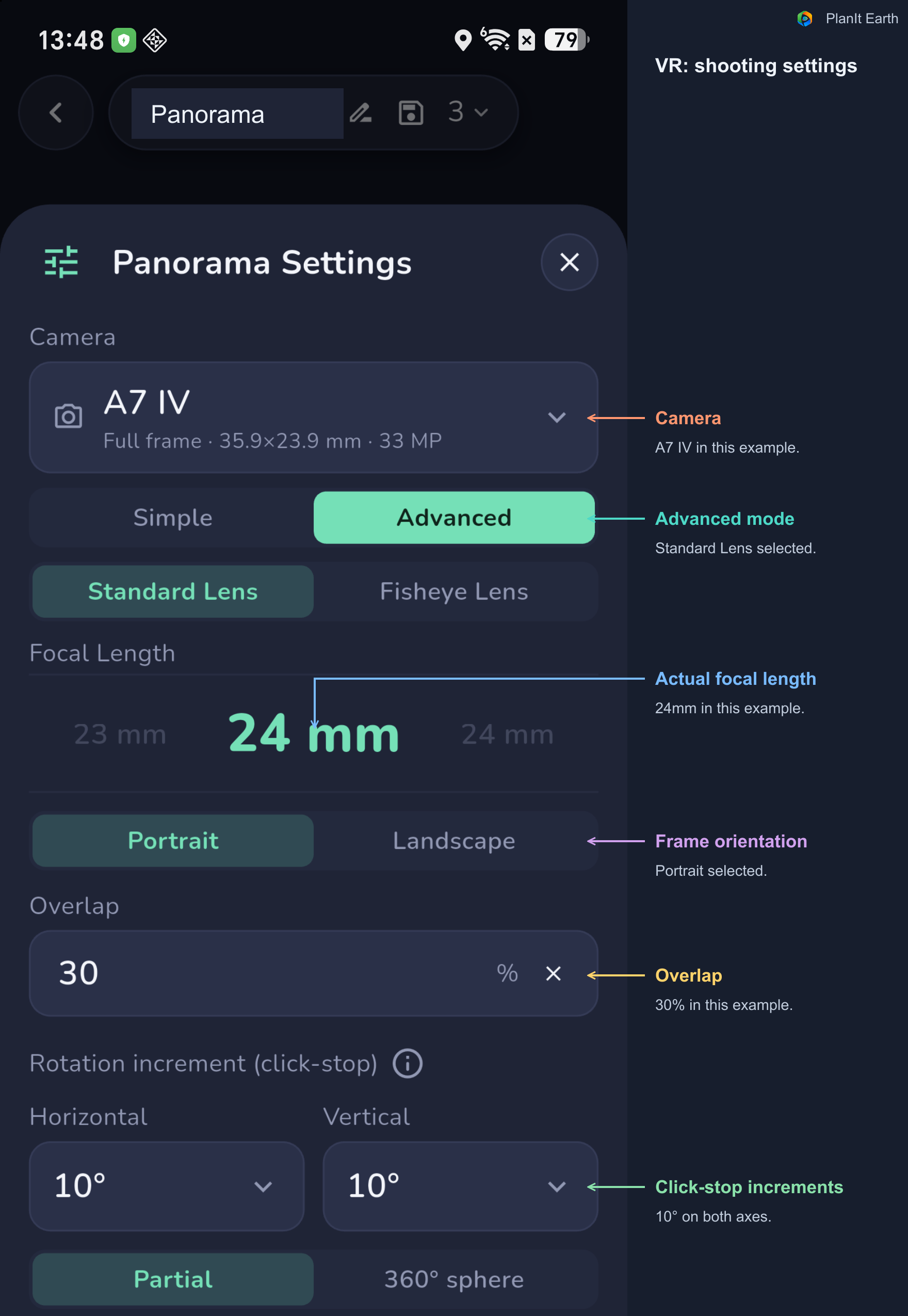
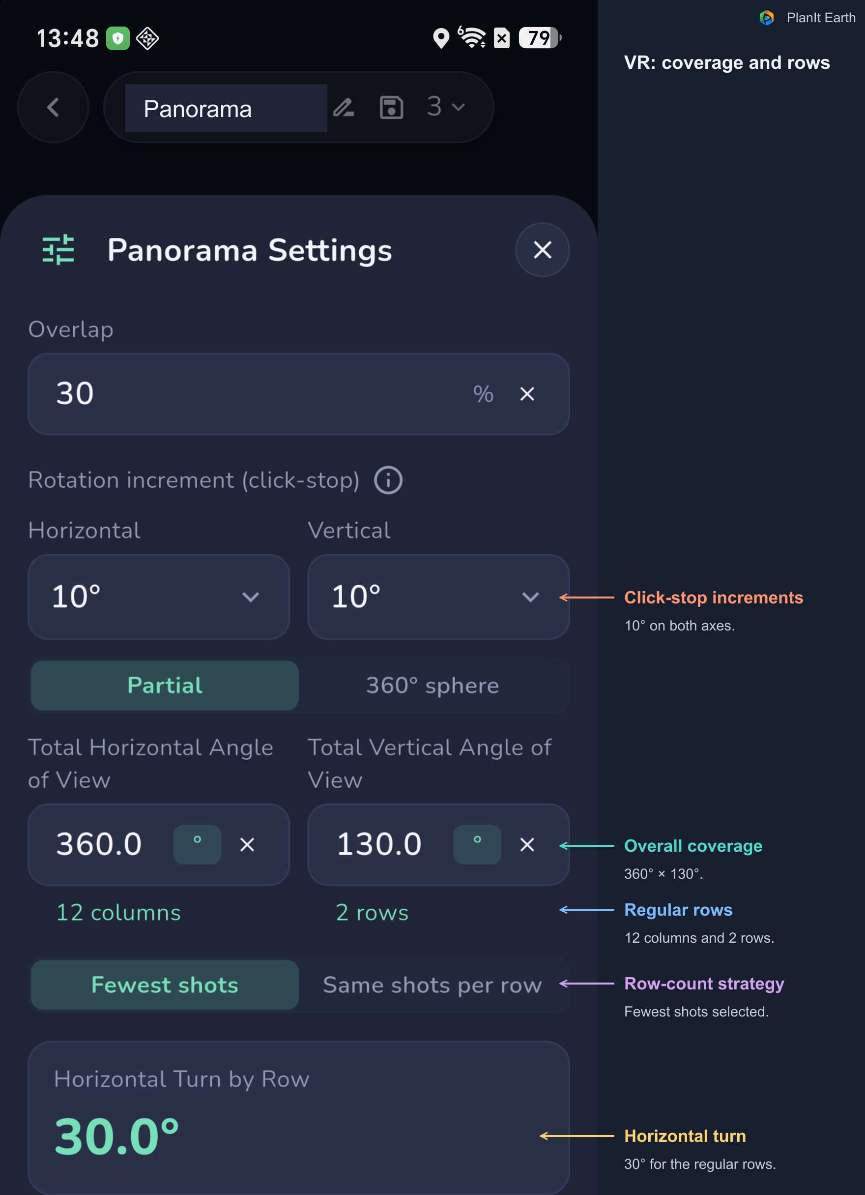
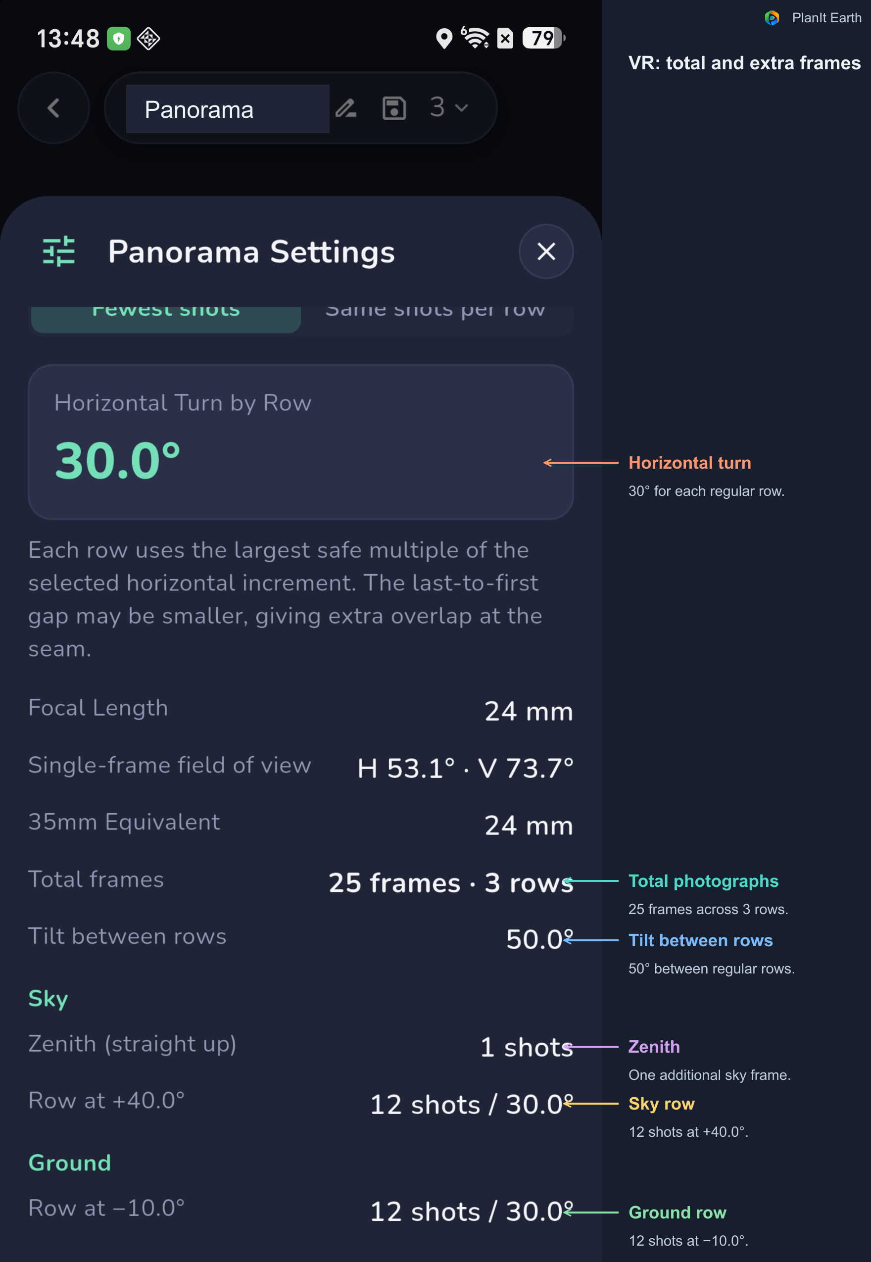
The VR example uses a 24mm standard lens in Portrait orientation, with 30% overlap and 10° horizontal and vertical increments. These settings differ from the Landscape card example, so read the results for this plan.
Scroll through the settings to check the coverage and row details. Do not stop at the total shot count: check each row's elevation and horizontal turn, including any separate zenith or nadir shot.
Adjust View: choose the overall coverage
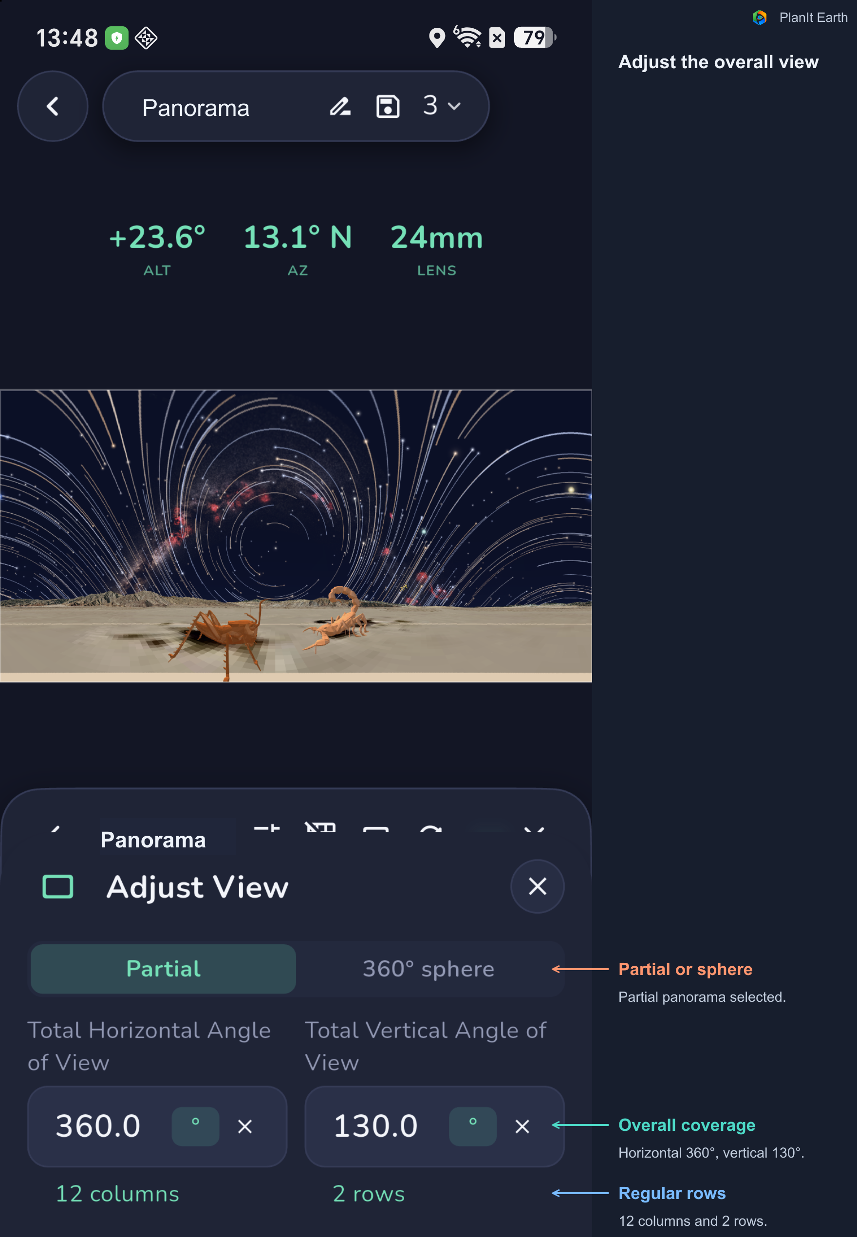
Select a partial panorama or a full sphere, then adjust the horizontal and vertical coverage. Back in the preview, drag to change the overall direction and elevation.
The illustrated coverage arrangement has two regular rows. The results also include a separate zenith frame, making 25 frames across three rows in total. The overall panorama coverage is different from the field of view of one source photograph.
Photo Areas: check each frame
Tap Photo Areas to display all rows, select a particular row, or inspect one photograph within that row. The panel shows row information and whether it covers sky, ground, or both.
Check the edges, the sky–ground boundary, overlap between rows, and the seam between the first and last frames of a complete turn.
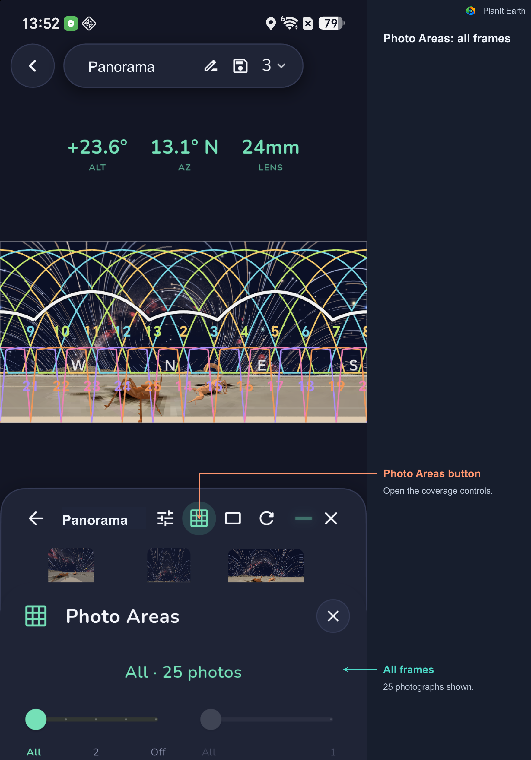
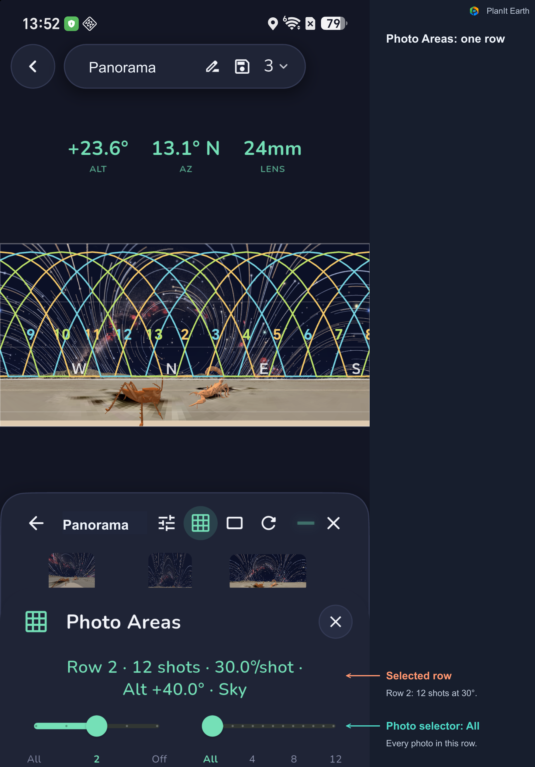
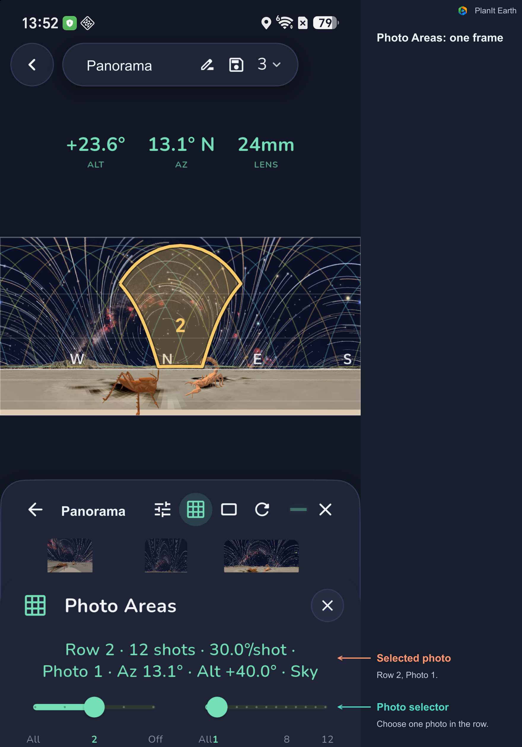
Why is the coverage of one photograph not rectangular? The yellow area shows where one photograph falls within the current panorama projection. Its outline can curve with the projection and camera direction; the photograph you capture is still rectangular. In this Mercator example, the camera points high into the sky. The part nearer the zenith is stretched more in the panorama, producing a curved outline that is wider at the top.
Use the left slider to select all rows or a particular row. After selecting a row, use the right slider to isolate one photograph. In this example, the first photograph of the second row is labeled 2 in the scene because the outlines use the overall plan numbering; number 1 belongs to the zenith frame.
The outlines are planned coverage, not photographs already captured by your camera.
Render: update the scene
After changing the location, time, or sky display, check whether the scene needs an update. Tap Render and wait for it to finish. Rendering creates a simulated preview; you still need to photograph and stitch the source images.
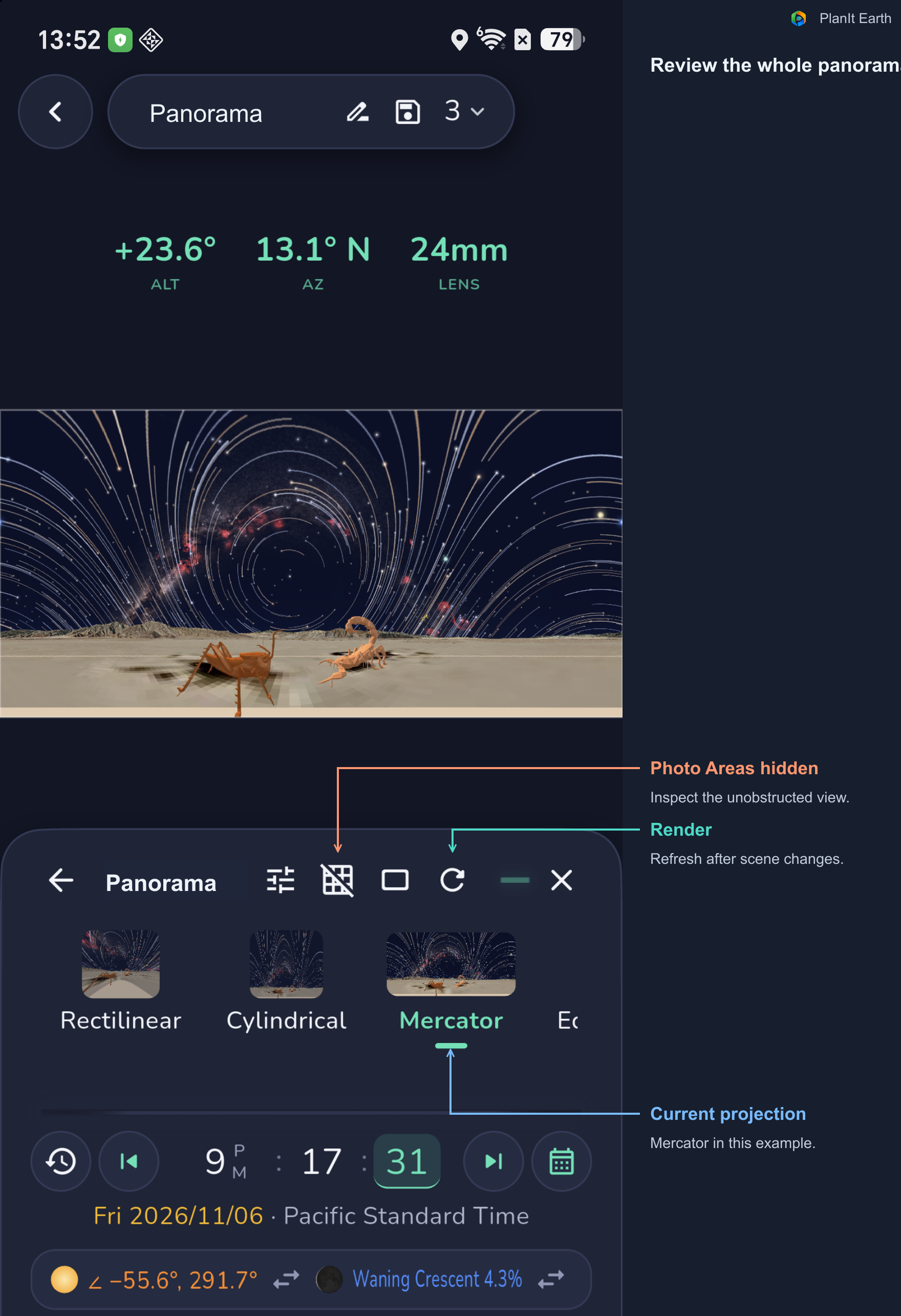
7. Compare twelve projections of the same scene
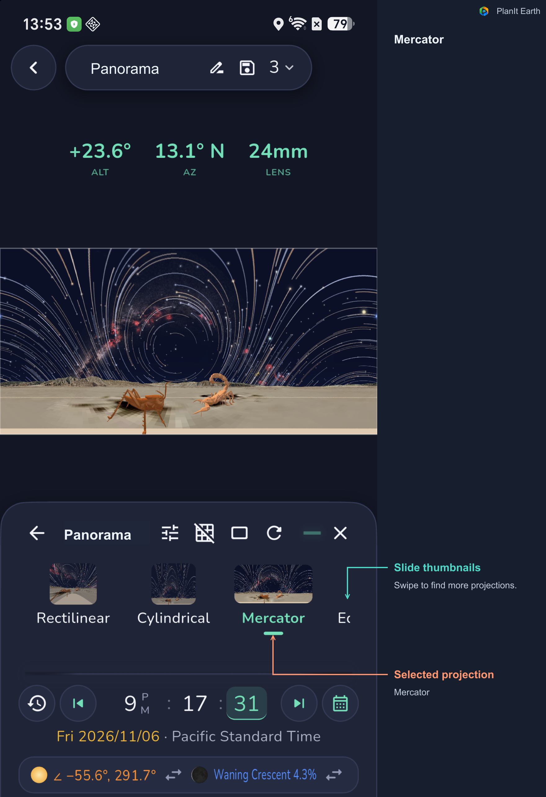
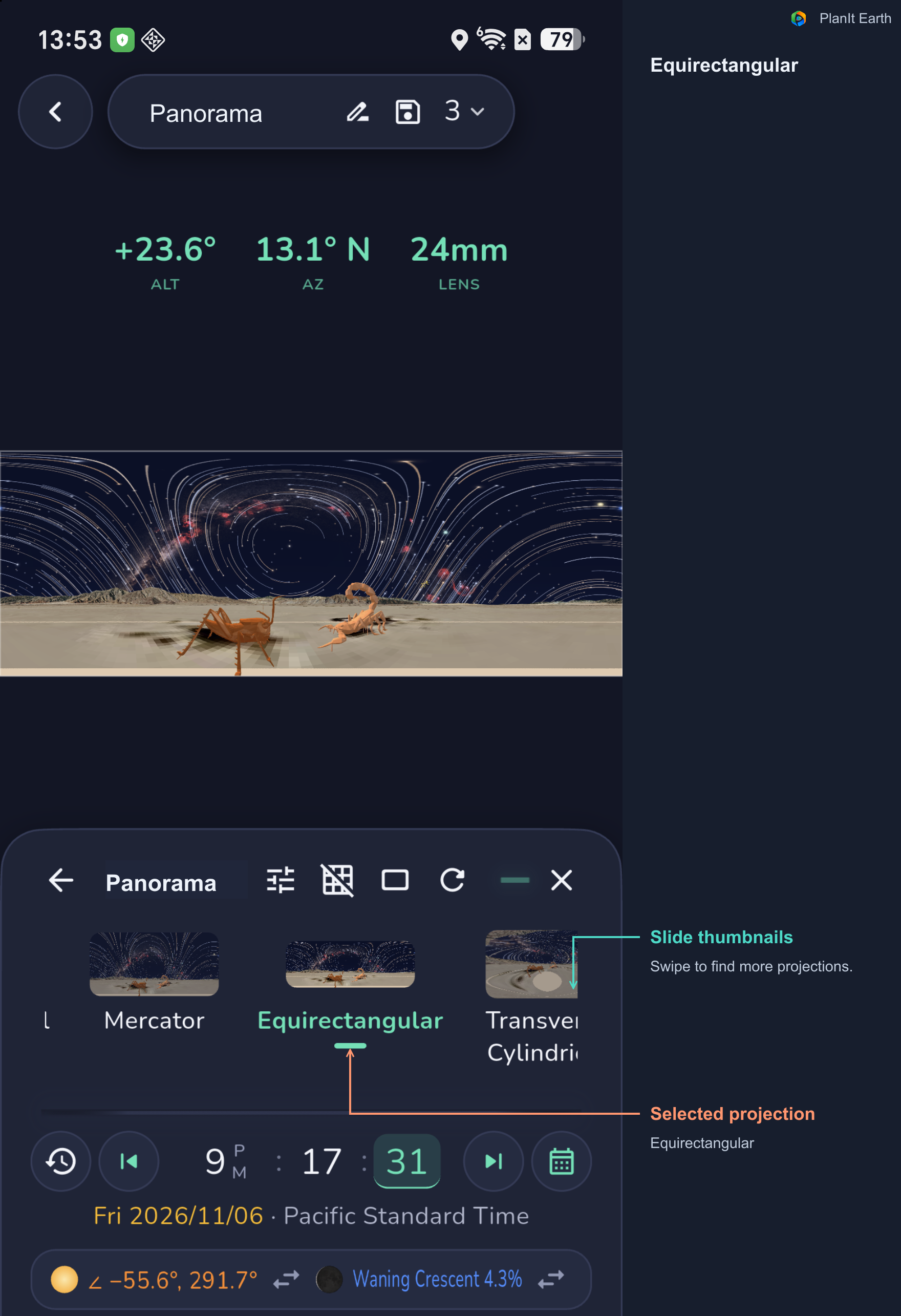
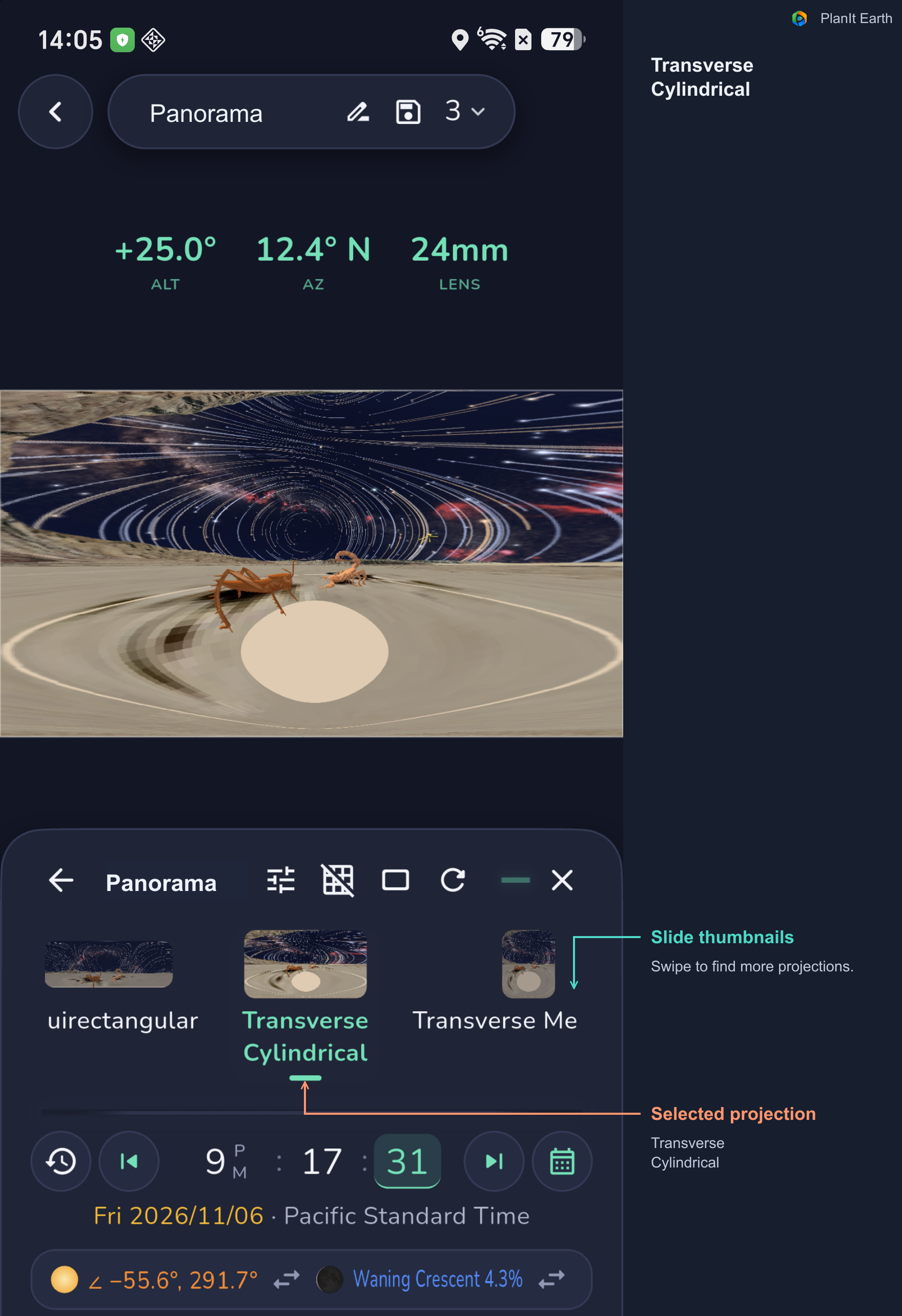
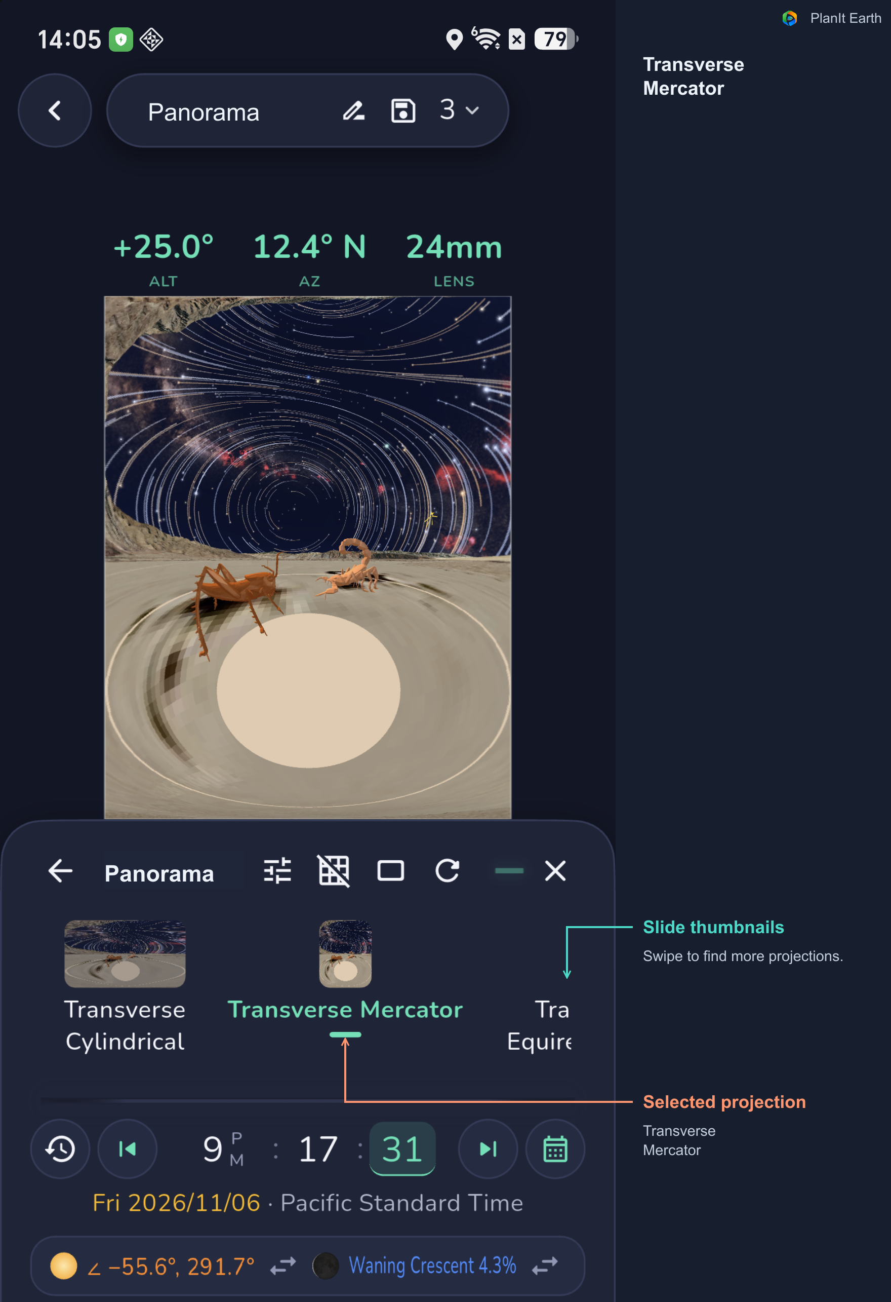
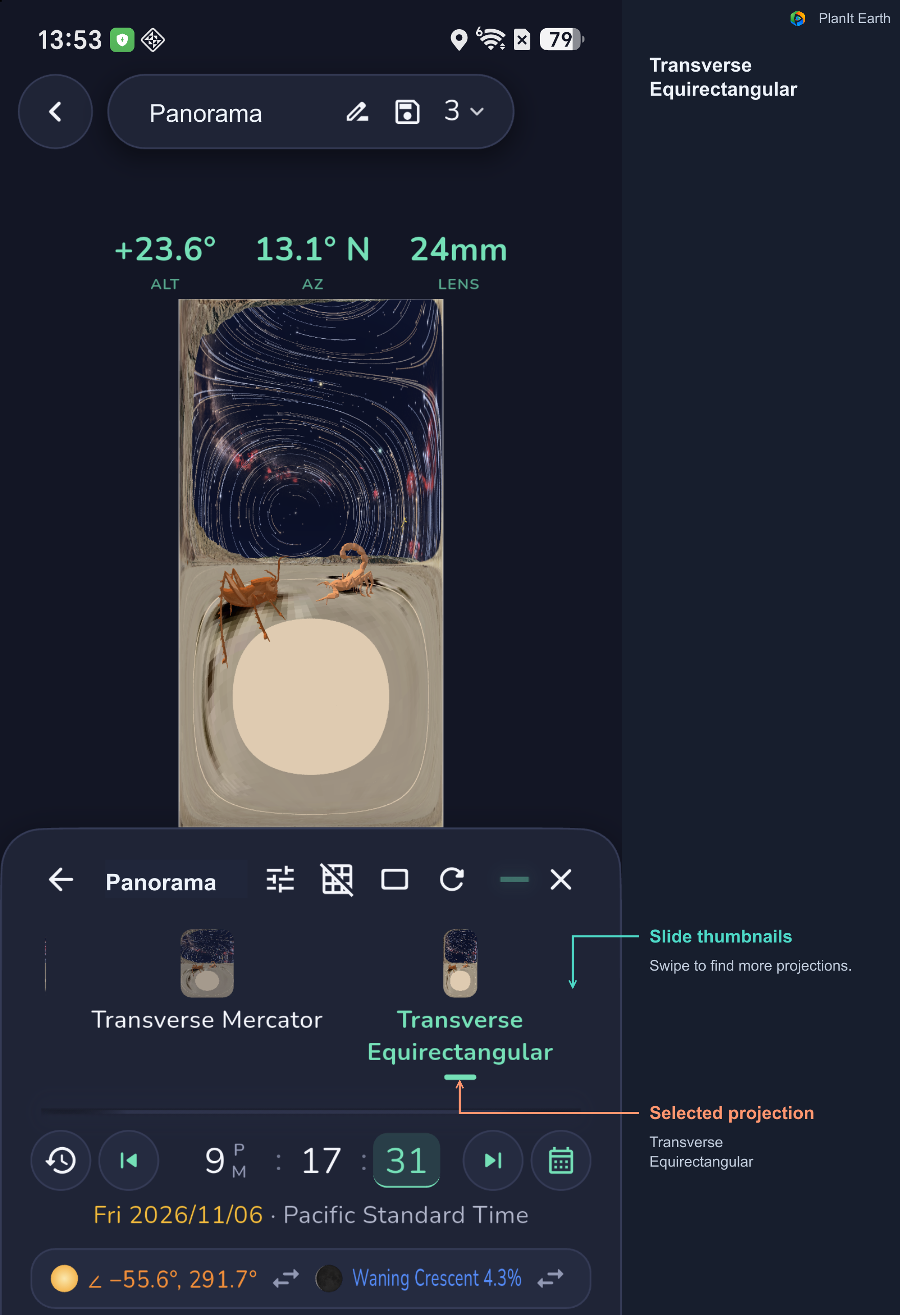
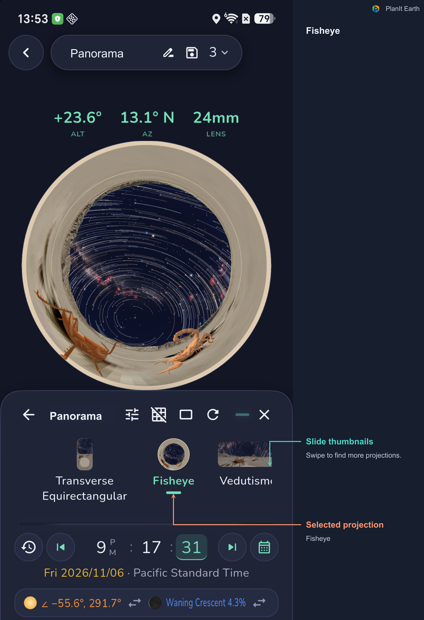
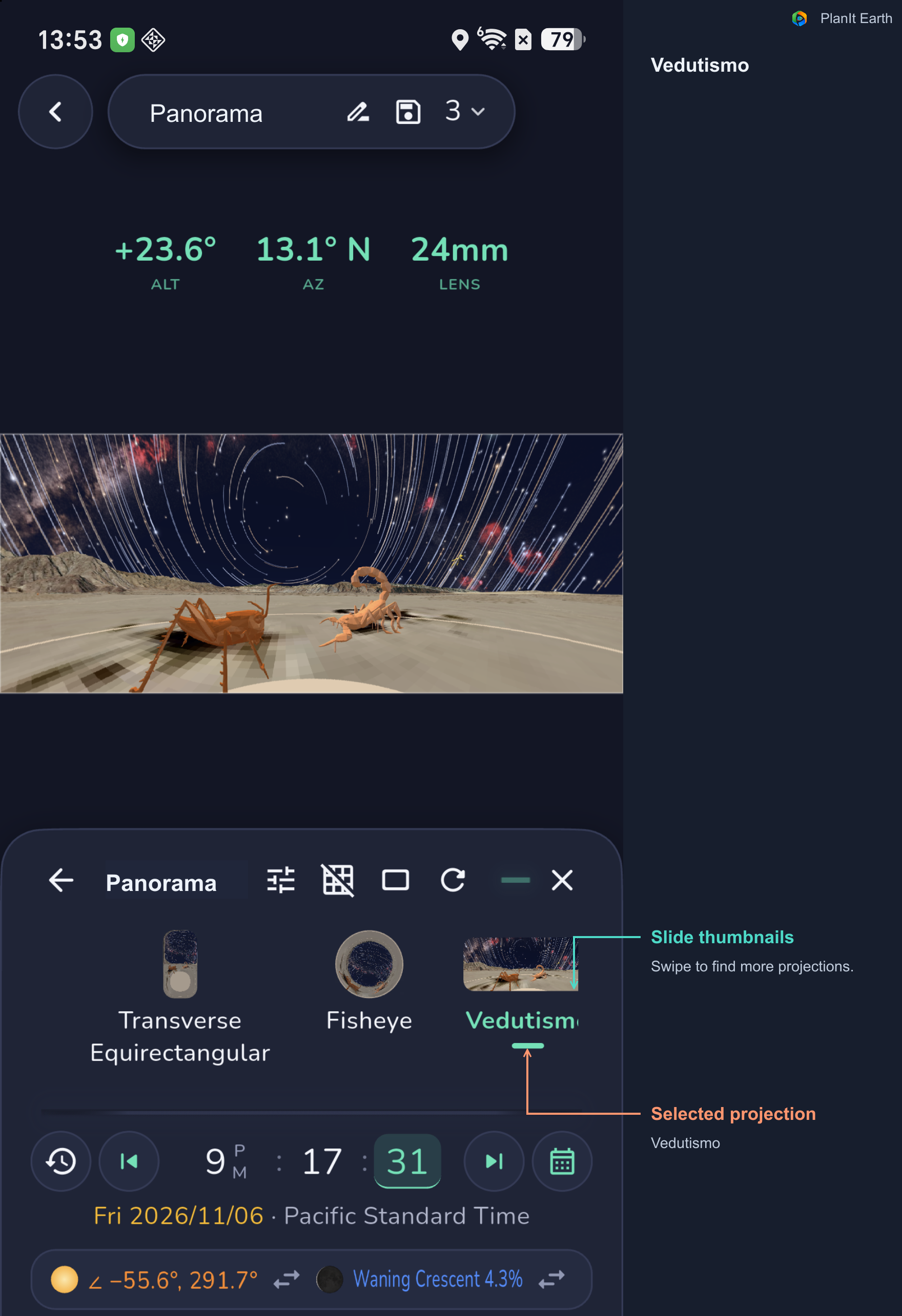
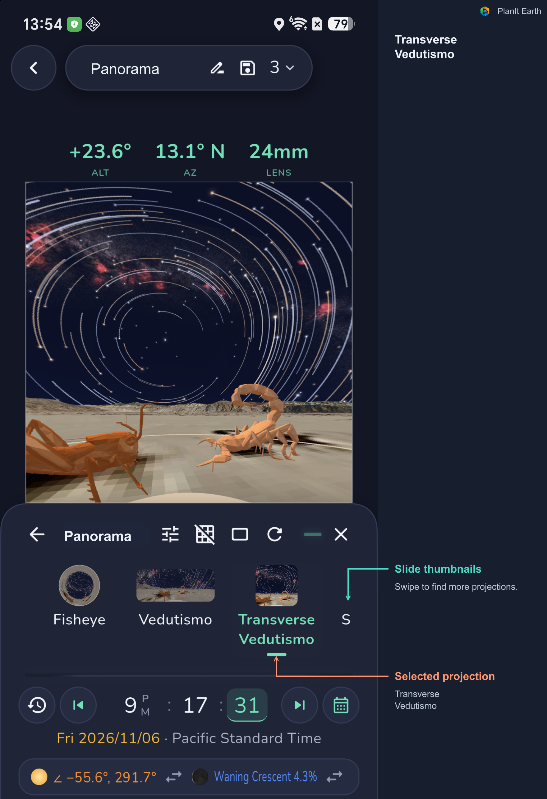
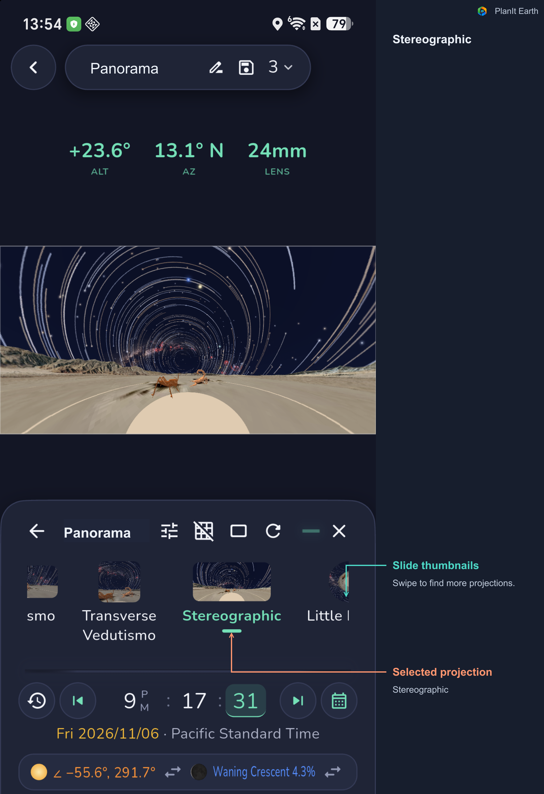
A panorama must map a surrounding space onto a flat image. The VR simulation provides twelve projections, allowing you to compare the shapes of the terrain, sky, and image edges.
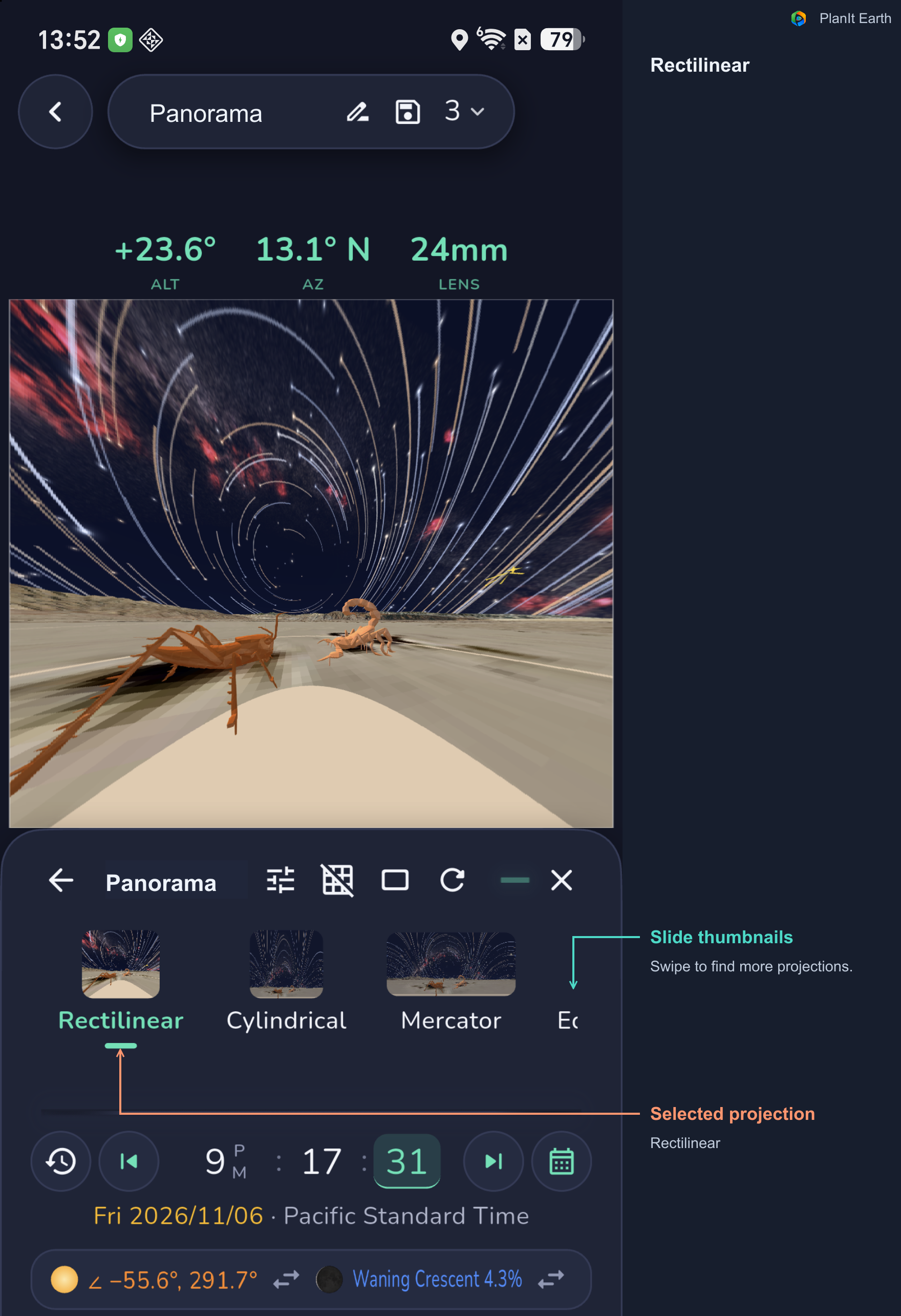
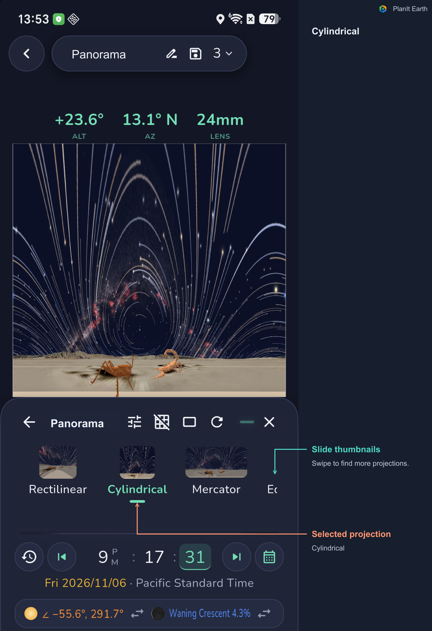
Rectilinear, Cylindrical, and Equirectangular. Rectilinear preserves straight lines, but very wide views stretch strongly near the edges. Cylindrical provides a horizontal wraparound view. Equirectangular can represent a complete 360° × 180° sphere.
Mercator, transverse variants, and Vedutismo. Compare how these spread the image and stretch the sky and foreground. The transverse variants provide another way to organize the scene around a different axis.
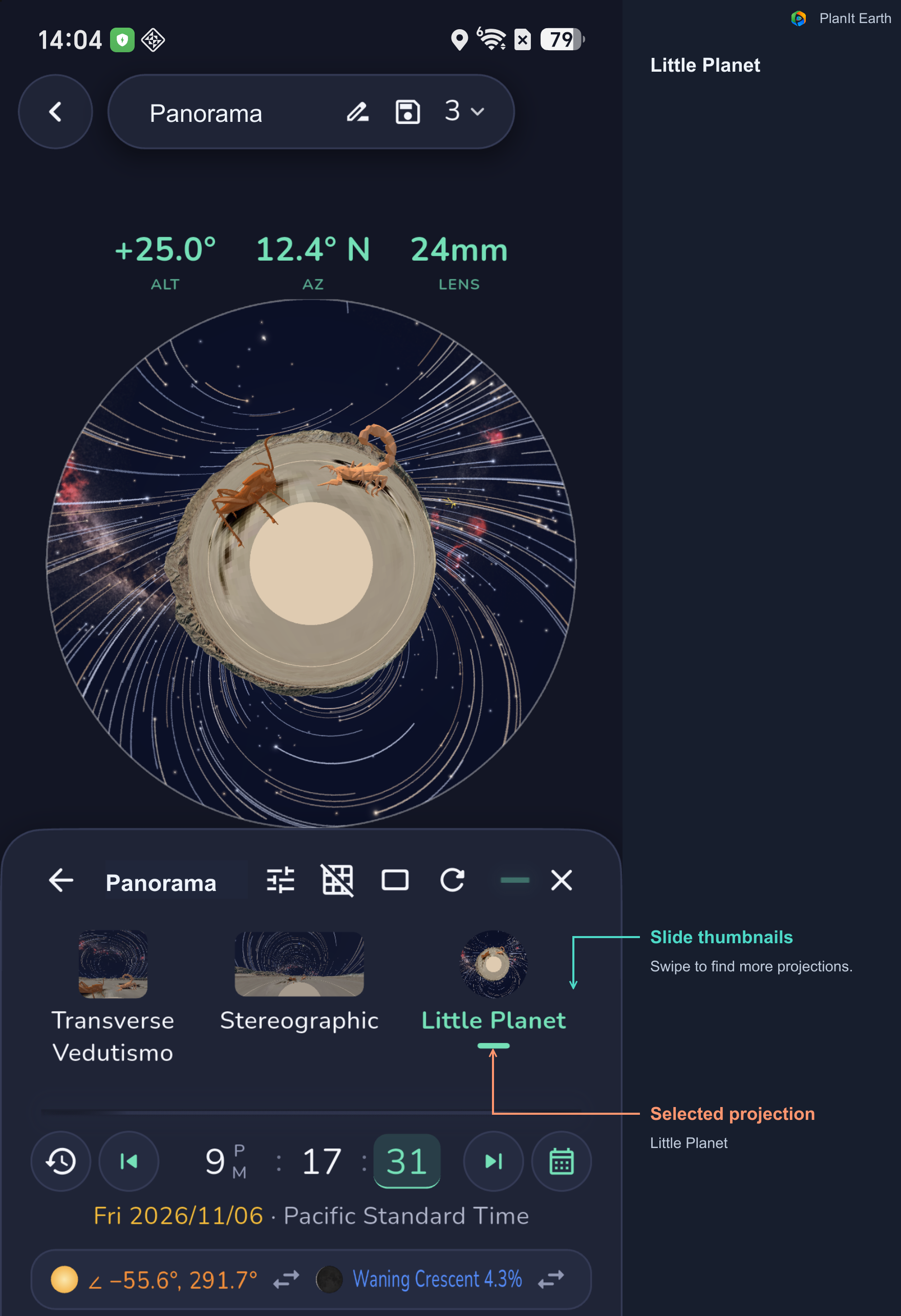
Fisheye, Stereographic, and Little Planet. These offer circular or strongly curved arrangements of sky and ground. Little Planet places the surrounding landscape around the center. For background on the projection types, see PTGui's projection guide.
In PlanIt Earth's panorama simulation, Fisheye and Little Planet use a complete horizontal turn and adjust the coverage accordingly. Check the shooting plan again after switching projections.
Your capture lens and final projection are separate choices. Photographs from a standard lens can be stitched into fisheye or little-planet views; fisheye source photographs can also be displayed using other projections.
Slide the thumbnails to find every projection
Scroll the projection strip horizontally to reveal more choices. These examples keep the same sculpture-and-star-trail scene so you can compare the changes.
8. Place a Milky Way arch above the landscape
Choose the camera position and shooting date, then adjust the time to see how the Milky Way sits above the landscape. If you want the arch to span a valley, building, or skyline, check both ends, the top of the arch, and the foreground in the same VR view.
Choose enough horizontal and vertical coverage to include the arch and its landscape. Turn on Photo Areas to check that the top is not clipped, that both ends have room, and that the lowest row includes the foreground you want.
Compare different projections to see how the arch and mountains spread across the image. Once you choose a composition, read the shot count and turn angle for each row.
A complete sequence takes time. The sky moves while you shoot, and different rows are photographed at different times. Account for that when planning the sequence and stitching the result.
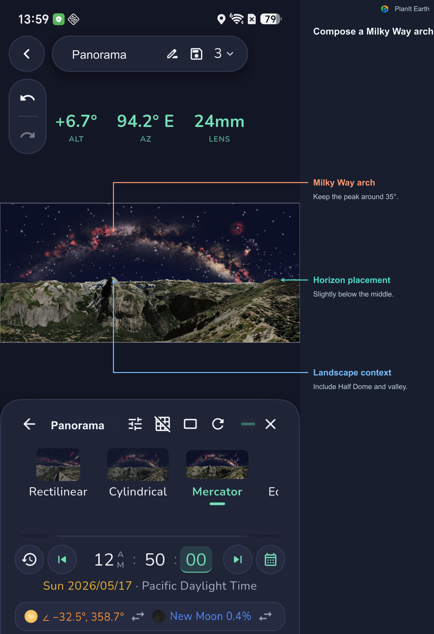
This example uses the Glacier Point area in Yosemite at 00:50 local daylight time on May 17, 2026, with a Mercator view covering approximately 220° × 90°. The top of the arch is around 35°, and the horizon sits slightly below the middle, leaving room for Half Dome, the valley, and both ends of the Milky Way.
The illustration uses a virtual camera 50 meters above the ground. It demonstrates the composition and should not be read as the view from an ordinary standing position at the overlook. Use your actual camera position and height, then check foreground obstructions again.
9. See how star trails wrap around the foreground
Enable Star Trails in VR Settings and choose a local nighttime. The current display accumulates trails from the end of astronomical twilight to the selected time. Moving later into the night lets you compare longer trails. Outside the corresponding nighttime interval, trails may not be displayed.
Use the panorama simulation to compare directions and projections. Position a mountain beneath the arcs, or let more of the sky surround a foreground subject, then inspect the coverage of each row.
After changing the star-trail settings, update the panorama and confirm that the trails appear before comparing the projections.
Real star-trail panoramas also require a time plan. Photographing different directions sequentially records different intervals in each area. Exposure timing and the stitching workflow affect whether the final trails can be joined convincingly. The simulation helps you judge their shapes and composition.
The Avoid Star Trails card is useful for a different goal: estimating exposures that keep stars as points, such as in Milky Way panoramas. Use VR's Star Trails display when planning visible arcs.
The sculpture examples above already show star trails. Compare a wide Mercator view with Fisheye, Stereographic, or Little Planet. Switching projection changes how the same scene is displayed; changing the nighttime and updating the scene changes the trail length.
10. Leave with a shooting sequence you can follow
Check the camera, actual focal length, source-frame orientation, and overlap. Choose partial coverage or a full sphere, match the click-stop settings to the head, and read the results row by row. Use VR to assess the whole composition, then check Photo Areas and the full-turn seam. Record each row's elevation, shot count, and turn angle, including any zenith and nadir frames.
In the field, keep exposure, white balance, and focus consistent across the sequence where practical. With close foreground subjects, check parallax as the camera rotates and adjust the rotation setup. For night-sky work, also plan the total shooting time, sky movement, and foreground exposures.
Start with a manageable single-row or multi-row panorama. Calculate the movements in PlanIt Earth, preview the complete composition in VR, and head out with a clear sequence.
11. Automatic Shooting: Not Yet Implemented
Once we have calculated a shooting plan and previewed the composition in VR, the next step is to let the equipment carry out the plan automatically. This is a direction we have long promised to pursue.
We plan to support motorized heads that can turn according to the panorama plan and work with the camera to capture each row and photograph. The Benro Polaris, which some users already own, is one of the devices we plan to support.
If you have another suitable motorized head or a new product to suggest, please tell me through Forum & Feedback in the menu. If the device provides a control interface we can use, there is an opportunity to let it execute the shooting plan calculated by PlanIt.
Exporting the shooting plan is another possibility. If your head-control software can import a particular format, please tell me the software’s name and its format requirements. We can consider supporting that export format so the software can handle the head movements and automatic shooting.
My goal is for PlanIt Earth to connect the whole process: from planning, simulation, and checking to controlling the equipment and capturing the photographs.